
  |
Site Layout and Foundation
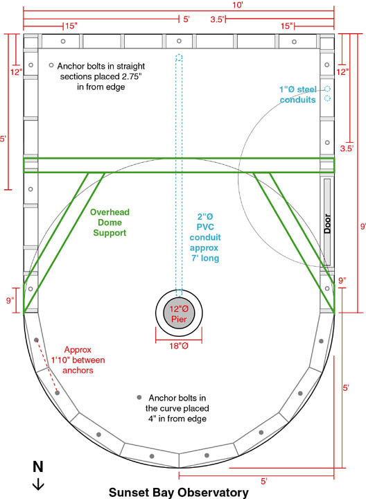
At right is a diagram of the observatory floor plan. (Current as of at least 28 July 2001, of course. Some features may change later.) It shows the critical dimensions, the dome centered over the pier, conduits, anchor bolt locations, rough framing plan, door swing, and the overhead dome support. Some of these features won't be discussed until the walls and roof are constructed. The important aspects for now, though, are the dimensions, conduits, and anchor bolts. This plan will be used to form and pour the concrete slab floor: its orientation, size, and position relative to the pier foundation, which has already been poured.
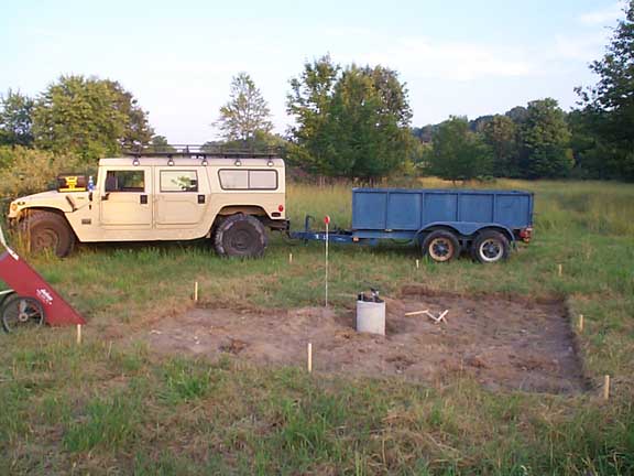
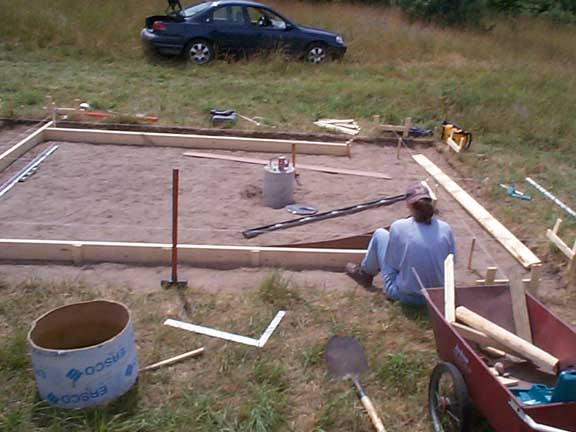
The first part of this job was to pull up the sod from the building area. Removing the sod turned out to be one of the hardest and dirtiest jobs in this entire project (second only to digging the foundation trench). The pier foundation was already in place, so the rough dimensions were measured from that point. The building will be 10' by 14', but a larger area (14' by 18') is cleared to allow working room around the forms. The building area was also oriented north-south; one end has a 30 degree pitched roof that will be covered in solar panels, so it needs to be oriented to the south. Then, the dirt "field" was raked to remove the surface rocks and smooth and level the area. Using batterboards and string guides, the forms for the three straight sides were constructed from 2x6 boards. The curved section will be formed in with 1/4" masonite, a strong but thin and flexible material.
Click on images to enlarge:
 Pulling Up the Sod |
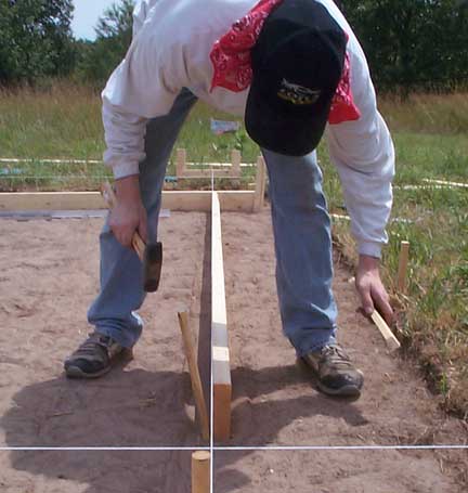 |
It is surprisingly difficult (and frustrating) to build perfectly straight, square, and level forms, even when using a transit (as we were). A lot of time was spent making sure the geometry was as perfect as possible (even right up to the morning of the pour). Then it was time to dig the perimeter trench that will act as the slab foundation. There was much debate as to how deep this trench needed to be. For larger structures, the depth would have to be in excess of 40" for this part of Michigan. For this application, though, it was determined that 30" is adequate. The actual trench was dug to about 28-30" deep, a practical limit for hand digging. At about 10" wide and 43.7' long, this job involved moving about 91 cubic feet of dirt! It was a big job to do by hand, but would have been a small and awkward job to hire an excavator, especially for the curved section.
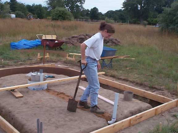
 Taking a Break to Recalculate Some Critical Dimensions |
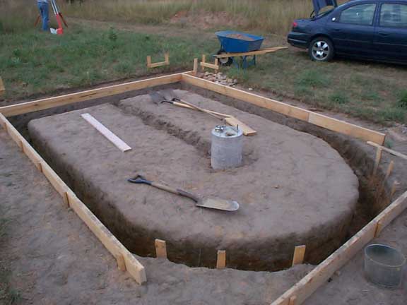 Digging a Trench for a Foundation |
There are two types of conduit to be used in the observatory. First, a 2" PVC conduit will run from the telescope pier to where the computer desk will be. This is for running power and/or computer cables back to the telescope and future accessories (like a CCD camera). This pipe has to be buried into the dirt underneath the concrete slab. Second, the two smaller steel conduits run from the wall near the southwest corner to just outside the foundation. This is for incorporating possible upgrades in the future like telephone, satellite access, weather station data, or electrical power. (In the meantime, the observatory will operate from solar power and batteries.)
 Burying the PVC Conduit |
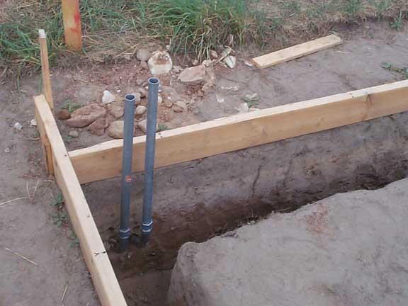 Conduits for Future Power and Telephone Lines |
Almost ready for the concrete truck! The forms are finished, level, square, and reinforced with stakes. The masonite forms were checked for the correct radius and reinforced with rocks and backfill. The 18" diameter sonotube is placed around the pier foundation with spacers and is leveled to be slightly above the outside forms so that the concrete will slope away from the gap around the pier. This will help rainwater drain off the slab until the rest of the observatory is built.
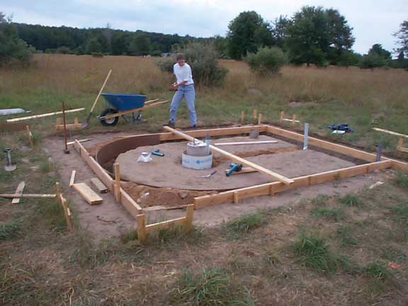 Almost Ready for the Concrete! |